
Lensed Fiber
Nanonics offers unique lensed and tapered fiber probes for optimal coupling to and from optical micro and nano devices such as waveguides, optical fibers, and diode lasers. Nanonics lensed fibers can be integrated with scanning probe microscopes and thus can be used for imaging and nanomanipulation. The lensed fibers are produced by glass pulling technology and IR laser shaping. Single-mode (SM), Multimode (MM), and Polarization maintaining (PM) lensed fibers for the wide range of wavelengths are available.

Key Features
Near-Field & Far-Field Optical Characterization with Nanometric Accuracy
Accurate tests of lens profiles can be performed with near-field optical microscopy, providing detailed optical properties of the lens. These tests are performed using simultaneous near-field/far- field optical techniques and AFM topographical imaging. Simultaneous topographic and NSOM measurements on the lensed fiber surface enable to test the centricity of the lensed fiber. NSOM characterization in X, Y and Z direction allows to get the focus spot size and working distance with nanometric resolution
Coupling With Sub-Micron Size Optical Devices
- Coupling with nanometric waveguides
- Coupling with nanometric optical detectors
- Coupling with nanometric lasers

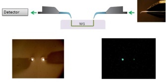
2. With two cantilever, near-field optical probes with exposed tips, light is injected through one probe and is guided through the sample which is a fiber. With the second probe in place, this injected light can be collected and analyzed both spatially and temporally. In this image two NSOM probes are seen in AFM contact with the input and output of the fiber waveguide.
Sub-Micron Spot Size
Nanonics offers lensed fibers with spot sub micron spot size for the most effective coupling with optical nanodvices.


Integration with Multiprobe Scanning Systems for Photonics and Plasmonic Research
Mix-and-match probes and nanoaligners employed lensed fibers for imaging and manipulation – Photonics/Plasmonics Meteorology Station.


Specifications


| Lensed Fiber | Spot Size (μm) | Working Distance(μm) |
| SM 1300-1550nm | 1.7+0.3* | 4±1* |
| 2±0.3 | 6±1 | |
| 3±0.5 | 10±1.5 | |
| 4±0.5 | 13±1.5 | |
| 5±0.5 | 16±1.5 | |
| 6±0.5 | 18±2 | |
| 9±1 | 25±3 | |
| SM 488nm | 0.8+0.2 | 4±1 |
| 1±0.3 | 6±1 | |
| 2±0.3 | 9±1.5 | |
| 3±0.5 | 12±1.5 | |
| 4±0.5 | 16±2 | |
| SM 780nm | 1+0.3 | 4±1 |
| 2±0.5 | 7±1 | |
| 3±0.7 | 10±1.5 | |
| 4±1 | 14±1.5 | |
| 5±1 | 25±3 | |
| SM 1060nm | 1.5+0.3 | 4±1 |
| 2±0.3 | 6±1 | |
| 3±0.5 | 13±2 | |
| 4±0.5 | 15±2 | |
| 5±0.7 | 17±2 | |
| 6±0.7 | 19±2 | |
| 8±1 | 25±3 | |
| PM 1550nm | 2±0.5 | 5±1 |
| MM VIS-IR | Minimum: 5±1 | 5±1 |
| Maximum: 50±2 | 50±3 | |
| MM UV | Minimum: 6±1 | 6±1 |
| Maximum: 50±3 | 50±3 |
Numerical Aperture of the Lensed fibers can be calculated using the following formula:
NA=2λ/πd where d is spot size
High accuracy spot diameter and working distance characterization can be achieved with near-field microscopy by special request.

r = Radius of Curvature. α = Angle of Fiber Bend.
- Tapered, bent lensed fiber.
- Customization
- Bent Lensed Fibers
- Metal Coating
- Cables
- Ferrule
- Connections with SMA, FC, ST, SC
Inquiries/Place Your Order
Contact a Nanonics Specialist to Discuss Your Specific Needs
We are happy to answer all questions and inquiries